Laser Deflection Systems
Conoptics' electro optic deflection systems are designed to efficiently change the angle of a laser beam with high precision. These systems can scan a laser beam across various angles or control its output angle with great accuracy. By utilizing a quadrapole electric field within an electro-optic material, they create ...
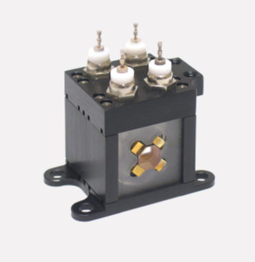
Conoptics has developed the Model 320 Electro-Optic Nutator for deflecting an optical beam in two orthogonal axes. The Model 320 Nutator is used to scan linearly polarized collimated beam over the clear aperture of a focusing lens at a wavelength of 1550nm.
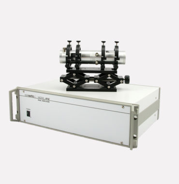
Conoptics has developed a deflection system for optical trapping called the Model 412 2-Axis Electro-optic Deflection system. This system includes two deflectors and a dual linear amplifier