Laser Modulation Systems
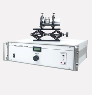
Conoptics manufactures a line of laser accessories, including driver electronics, beam deflectors, noise reduction tools, and optical isolators, all designed to meet diverse **modulation systems configuration options**. All electro-optic modulators listed in this data sheet are of the transverse field type, where the electric field produced by the applied ...
We have developed an E-O Multiphoton Microscopy system designed for the Insight DS+ and Chameleon Discovery lasers, operating in the 680nm-to-1300nm wavelength range. This system enhances performance by allowing precise control over laser intensity, ensuring high-resolution imaging for various research applications.
Conoptics manufactures a range of laser accessories designed specifically for Multiphoton Microscopy (MPM), including laser modulation systems, driver electronics, beam deflectors, noise reduction tools, and optical isolators. As a leader in the field, Conoptics has developed specialized solutions that optimize the performance of MPM systems, ensuring precision and reliability ...
Conoptics manufactures a line of laser accessories for laser modulation, driver electronics, beam deflectors, noise reduction and optical isolators. Conoptics’ a pioneer in the manufacturing of optics and laser accessories has developed a solution for Ultra Violet Multi-Photon Microscopy.
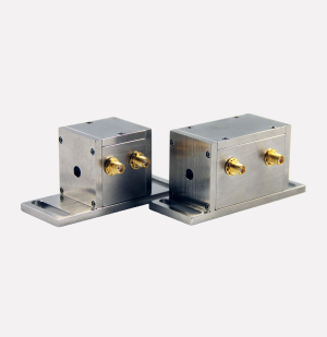
Conoptics manufactures a line of laser accessories for laser modulation, driver electronics, beam deflectors, noise reduction and optical isolators. Conoptics’ new line of High-Frequency phase modulators up to 500MHz.
Conoptics manufactures a range of laser accessories, including driver electronics, beam deflectors, and noise-reduction tools. As a pioneer in optics and laser accessories, Conoptics offers high-quality Phase Modulators designed for efficient laser modulation.

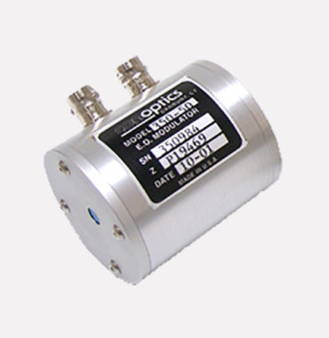
Conoptics manufactures a line of laser accessories for laser modulation, driver electronics, beam deflectors, noise reduction and optical isolators. Conoptics manufactures a complete line of Electro-Optic Modulation Phase Modulation Systems designed to work specifically with Pound Drever-Hall.
Conoptics manufactures a line of laser accessories for laser modulation, driver electronics, beam deflectors, noise reduction and optical isolators. Conoptics manufactures a complete line of Electro-Optic Modulation Shutter Systems designed to work specifically with Single Molecule Fluorescence Polarization.
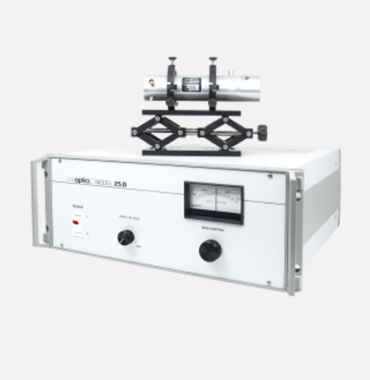
Conoptics manufactures a line of laser accessories for laser modulation, driver electronics, beam deflectors, noise reduction and optical isolators. Conoptics manufactures a complete line of Electro-Optic Modulation Shutter Systems designed to work specifically with Time Doman Thermo reflectance (TDTR).
Conoptics manufactures a line of laser accessories for laser modulation, driver electronics, beam deflectors, noise reduction and optical isolators. Conoptics manufactures a complete line of Electro-Optic Modulation Shutter Systems designed to work specifically with High-Power Laser Machining.