Domestic: (800) 748-3349 – International: (203) 743-3349
Fiber lasers pack a lot of gain into a small, elegant package — and that same tight confinement makes them unusually sensitive to light that finds its way back where it came from. A stray reflection off a connector, a splice, or a workpiece can travel backward through the fiber and reach the gain medium or pump diodes before anyone notices a problem.
Have you ever watched a fiber laser’s output power drift for no obvious reason, or seen a pump diode fail well ahead of its rated lifetime? Back-reflection is often the quiet cause. It rarely announces itself with a dramatic failure; instead it shows up as instability, gradual degradation, or an intermittent fault that is hard to reproduce on the bench.
We want to walk through why this happens, what it costs a laser system over time, and how a properly specified optical isolator addresses it. The physics involved is well understood, and the fix is more approachable than it might first appear.
Why Fiber Lasers Are Especially Vulnerable
In free-space laser systems, a reflected beam often diverges and misses the cavity entirely. Fiber systems don’t get that luxury. Once light couples back into the core, the fiber itself guides it efficiently in the reverse direction, straight back toward the gain fiber, the pump combiners, and the diodes that supply them.
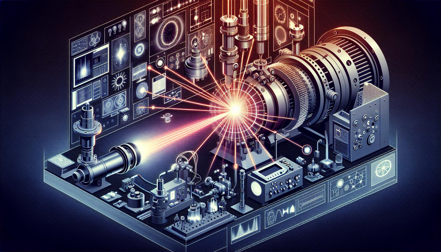
Reflection sources are everywhere in a real system. Connector interfaces, even angle-polished ones, return a small fraction of light. Fusion splices with slight index mismatches do the same. In laser machining and material processing, the workpiece surface itself — especially a specular metal — can reflect a meaningful fraction of incident power directly back down the beam path. Downstream optics, including lenses, windows, and scan mirrors, contribute their own small reflections at every uncoated or imperfectly coated surface.
None of these individual reflections need to be large to matter. Fiber lasers operate with high circulating intensity in a small mode field diameter, so even a reflection well below one percent can represent significant power density when it reaches sensitive components.
What Back-Reflection Actually Damages
The consequences fall into a few recognizable categories, and they compound.
Mode instability and mode hopping. Reflected light re-enters the cavity out of phase with the intended round-trip and disturbs the balance that keeps the laser operating on a stable longitudinal or transverse mode. The result is unpredictable jumps in output characteristics, sometimes visible as flickering in beam profile measurements.
Amplified spontaneous emission buildup. In fiber amplifiers, a reflected signal traveling backward through the gain fiber gets amplified just as the forward signal does. Left unchecked, this reverse-traveling ASE can build to levels that draw down the available gain, distort pulse shape, and in extreme cases trigger parasitic lasing within the fiber itself.
Gain fiber and pump diode damage. This is the most costly failure mode. Reflected power reaching the active fiber can produce localized heating and, at high enough intensity, catastrophic damage to the fiber core. Pump diodes are even more delicate — laser diodes are simply not designed to have light injected back into their own cavity, and doing so degrades their facets over time or destroys them outright.
Power and noise fluctuation. Even short of hard damage, back-reflection introduces amplitude noise and slow power drift that shows up as measurement noise in a microscopy system or inconsistent cut quality in a machining application.
How Faraday-Effect Isolators Solve the Problem
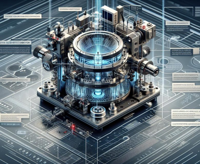
An optical isolator is a non-reciprocal device: light passes through it in the forward direction with minimal loss, but light traveling backward is blocked. That asymmetry is the entire point, and it depends on the Faraday effect.
A Faraday rotator uses a magneto-optic material inside an axial magnetic field. Light polarized in a given orientation passes through the material and has its polarization plane rotated by a fixed angle, typically 45 degrees. Critically, this rotation direction is defined by the magnetic field, not by the direction of light propagation. A standard polarization rotator (like a waveplate) would simply undo its own rotation on the return pass — a Faraday rotator does not.
A typical isolator pairs this rotator between two polarizers set 45 degrees apart. Forward-traveling light passes the first polarizer, gets rotated 45 degrees, and exits cleanly through the second. Light reflected back into the device passes through the second polarizer, gets rotated another 45 degrees by the same physical mechanism, and now arrives at the first polarizer rotated a full 90 degrees relative to its transmission axis — so it is blocked rather than transmitted. The non-reciprocity comes entirely from the magnetic field’s fixed direction, not from anything mechanical.
Specifications That Actually Matter
Isolator datasheets share several parameters worth scrutinizing before selection, and they interact with each other more than they might first suggest.
Isolation ratio, expressed in dB, describes how much backward-traveling power the device rejects. Higher is generally better, but the right number depends on how much reflected power the system is likely to generate; a machining head reflecting off bare metal warrants a different isolation budget than a low-power seed stage.
Insertion loss is the forward-direction cost of adding the isolator, and in a high-power amplifier chain even a few tenths of a dB translates into real heat that the housing has to manage. Power handling determines whether the isolator can survive continuous operation at the intended output level without thermally induced polarization drift, which quietly degrades isolation performance as the device warms up.
Wavelength range matters because Faraday rotators are wavelength-dependent; a rotator optimized for 1064 nm will not deliver the same isolation at 1550 nm. And polarization dependence is worth checking directly — some isolators require a defined input polarization state, which matters for placement after components that scramble or rotate polarization, such as certain fiber amplifier stages.
Where to Place Isolators in the Chain
Placement follows the vulnerability. A seed-stage isolator, immediately after the oscillator or seed diode, protects the most sensitive low-power source from reflections generated anywhere downstream — this is usually the highest-priority location in any amplifier chain. Isolators are also placed between amplification stages in multi-stage systems, preventing ASE and reflected signal from one stage from feeding back into the previous one and disturbing its gain dynamics.
At the output end, a final isolator between the last amplifier stage and the delivery optics or process head protects the entire chain from whatever the application throws back at it — connector interfaces, workpiece reflections, or downstream lens surfaces. In systems where back-reflection risk is high, such as metal processing, more than one isolation point along the chain is common practice rather than overengineering.
Working Through It With Our Engineering Team
Back-reflection problems tend to look like something else at first: a noisy signal, a diode that fails early, an inconsistent process result. Once isolation is identified as the cause, the fix is straightforward, but getting the isolation ratio, power handling, and wavelength specification right for a particular system takes some care.
If you’re seeing instability in a fiber laser or amplifier chain and suspect back-reflection is involved, our engineering team is glad to look at the specifics of your setup and help identify where isolation would do the most good. Contact us!