Domestic: (800) 748-3349 – International: (203) 743-3349
Key Takeaways
- Delay lines are electronic components that introduce precise time delays to signals, crucial for modern electronics and signal processing applications
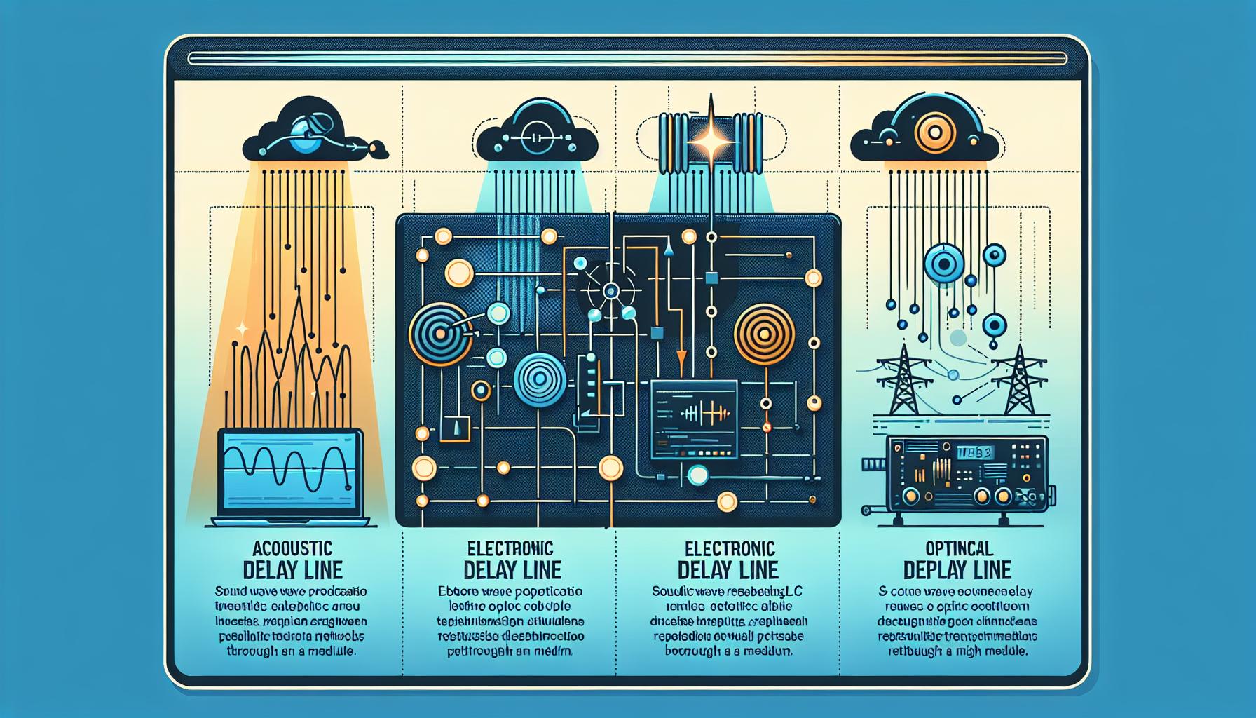
- Three main types exist: acoustic (using mechanical vibrations), electronic (using passive components), and optical (using light signals through fiber optics), each serving different timing needs
- Applications span multiple industries including audio processing (creating effects like echo), radar systems (target detection), and digital communications (data synchronization)
- Key performance parameters include delay time accuracy (±1% to ±10%), signal loss (0.5-3 dB per unit), and temperature stability (±0.1% per °C)
- Modern delay line technologies like Surface Acoustic Wave (SAW) devices and digital delay lines offer improved precision, programmability, and reliability for contemporary electronic systems
Have you ever wondered how electronic devices process signals with perfect timing? We use delay lines – fascinating electronic components that temporarily hold and delay signals for precise intervals.
Delay lines play a crucial role in modern electronics by controlling signal timing and synchronization. From radar systems to digital audio equipment these devices help manage complex signal processing tasks. Whether it’s creating echo effects in music or ensuring data arrives at the right moment in computer systems delay lines make it all possible.
We’ll explore how these essential components work their different types and why they’re so important in today’s technology. If you’re curious about the technology behind synchronized signals and precise timing in electronics you’re in the right place.
What Is a Delay Line and How Does It Work
A delay line is an electronic component that introduces a specific time delay to an electrical or electromagnetic signal. The signal enters at one point and emerges identical but delayed by a predetermined amount of time, ranging from nanoseconds to milliseconds.
Basic Components of Delay Lines
Delay lines consist of three primary elements:
- Input terminals that receive the original signal
- Transmission medium (coaxial cable, optical fiber, or acoustic material)
- Output terminals that deliver the delayed signal
The transmission medium determines key characteristics:
| Medium Type | Typical Delay Range | Signal Loss |
|---|---|---|
| Coaxial Cable | 1-100 ns | Low |
| Optical Fiber | 0.1-10 μs | Very Low |
| Acoustic | 1-1000 μs | Medium |
Signal Propagation Principles
Signal propagation in delay lines follows these core processes:
- The input signal travels through the transmission medium at a fixed velocity
- Each section of the medium adds incremental delay
- The signal maintains its waveform shape during transmission
- The total delay equals the medium length divided by the propagation speed
Physical properties affect delay time:
| Property | Impact on Delay |
|---|---|
| Temperature | ±0.1% per °C |
| Frequency | Up to 5% variation |
| Voltage | ±1% per volt |
The delay time remains stable under normal operating conditions when the transmission medium’s physical properties stay constant. Temperature compensation circuits adjust for environmental changes in precision applications.
Types of Delay Lines
Delay lines come in three primary categories, each using different physical principles to achieve signal delays. These technologies offer specific advantages for various applications based on their delay characteristics, bandwidth capabilities, and operating environments.
Acoustic Delay Lines
Acoustic delay lines convert electrical signals into mechanical vibrations that travel through solid or liquid media. These devices use piezoelectric transducers at both ends to transform electrical energy into sound waves and back. Common materials include quartz, glass, or mercury, providing delays from 1 to 10 milliseconds. The delay time depends on:
- Sound wave velocity in the medium
- Physical length of the transmission path
- Temperature of the operating environment
- Frequency range of input signals
Electronic Delay Lines
Electronic delay lines use passive components to create signal delays through electromagnetic principles. Three main types include:
LC Networks
- Utilize inductors and capacitors
- Provide delays of 1 to 1000 nanoseconds
- Support high-frequency applications up to 500 MHz
Transmission Lines
- Based on coaxial cables or microstrip lines
- Create delays through controlled impedance paths
- Offer bandwidth up to several gigahertz
Digital Delay Lines
- Use shift registers or memory elements
- Generate precise delays through clock cycles
- Enable programmable delay settings
Optical Delay Lines
Optical delay lines transmit light signals through fiber optic cables or free-space paths. Key features include:
- Ultra-low signal loss over long distances
- Immunity to electromagnetic interference
- Delays from picoseconds to microseconds
- Bandwidth capabilities exceeding 100 GHz
Applications include:
- Optical communication systems
- Laser pulse synchronization
- Optical coherence tomography
- Quantum computing experiments
Each type offers specific delay ranges and signal preservation characteristics. Optical lines excel in high-speed applications, acoustic lines provide longer delays, while electronic lines balance cost and performance for general use.
Common Applications of Delay Lines
Delay lines serve critical functions across numerous industries where precise signal timing matters. These specialized components enable sophisticated operations in audio systems, radar equipment, and digital communications networks.
Audio Processing and Effects
Audio delay lines create time-based effects like echo, reverb, and chorus in professional sound systems. The delay timing ranges from 10 microseconds to 500 milliseconds, producing distinct sonic characteristics for different musical applications. Digital audio workstations use multiple delay taps to simulate various acoustic spaces and create complex modulation effects.
Radar Systems
Radar systems employ delay lines for target detection and tracking through precise signal timing control. The components:
- Compare transmitted and received signals to calculate the target distance
- Align multiple radar pulses for improved detection accuracy
- Buffer incoming signals for sequential processing
- Enable moving target indication by comparing sequential radar returns
| Radar Application | Typical Delay Range |
|---|---|
| Short-range detection | 1-10 microseconds |
| Medium-range tracking | 10-100 microseconds |
| Long-range surveillance | 100-1000 microseconds |
Digital Communication
Digital delay lines synchronize data streams in communication networks and computer systems. Key applications include:
- Clock signal distribution in high-speed digital circuits
- Bit alignment in serial data transmission
- Pipeline stages in digital processors
- Jitter reduction in data recovery circuits
The delay times typically range from 1 nanosecond to 1 microsecond, depending on the specific communication protocol and data rate requirements.
Key Performance Parameters
Delay lines perform based on critical measurable characteristics that determine their effectiveness in signal processing applications. These parameters define the operational limits and capabilities of delay line systems.
Delay Time and Accuracy
Delay time accuracy impacts the precision of signal timing in electronic systems. Digital delay lines achieve accuracies of ±1% to ±5% of the nominal delay value, while analog versions typically range from ±5% to ±10%. Environmental factors like temperature variations affect delay stability by ±0.1% per degree Celsius, requiring compensation circuits in sensitive applications.
| Delay Line Type | Typical Accuracy Range | Temperature Coefficient |
|---|---|---|
| Digital | ±1% to ±5% | ±0.1%/°C |
| Analog | ±5% to ±10% | ±0.2%/°C |
Signal Loss and Distortion
Signal integrity decreases as signals travel through delay lines due to attenuation and dispersion effects. Typical insertion losses range from 0.5 dB to 3 dB per unit length, depending on the transmission medium. High-frequency components experience greater attenuation, leading to pulse broadening and potential intersymbol interference in digital systems.
| Parameter | Typical Values | Impact Factors |
|---|---|---|
| Insertion Loss | 0.5-3 dB/unit | Frequency, medium type |
| Bandwidth | DC-500 MHz | Line length, material |
| Return Loss | >20 dB | Impedance matching |
- Phase distortion: Measured in degrees per unit bandwidth
- Amplitude ripple: ±0.5 dB across the passband
- Group delay variation: <1% across an operating frequency range
Modern Delay Line Technologies
Modern delay line technologies leverage advanced materials and digital processing to achieve precise timing control with minimal signal degradation. These innovations expand the capabilities of traditional delay line systems while improving reliability and performance.
Surface Acoustic Wave Devices
Surface Acoustic Wave (SAW) devices operate by converting electrical signals into acoustic waves that travel across a piezoelectric substrate. These devices achieve delays between 1-50 microseconds with an insertion loss of 10-30 dB. The acoustic waves propagate at velocities of 3000-4000 meters per second, creating compact designs for specific frequency ranges from 10 MHz to 3 GHz. SAW devices excel in applications requiring:
- Fixed delay times with temperature stability of ±50 ppm/°C
- Narrow bandwidth filtering with 2-5% of center frequency
- High-frequency operation in RF systems
- Small form factors for portable electronics
Digital Delay Lines
Digital delay lines transform analog signals into digital format for precise timing control through memory-based systems. These devices offer:
- Programmable delays from 1 nanosecond to 1 second
- Delay accuracy within ±0.1%
- Multiple taps for simultaneous different delay outputs
- Temperature stability of ±10 ppm/°C
- Built-in signal conditioning circuits
- Automatic calibration capabilities
- Interface compatibility with modern digital systems
- Low power consumption at 50-200 mW per channel
| Parameter | Digital Delay Lines | SAW Devices |
|---|---|---|
| Delay Range | 1 ns – 1 s | 1-50 µs |
| Accuracy | ±0.1% | ±1% |
| Bandwidth | DC – 500 MHz | 10 MHz – 3 GHz |
| Power Usage | 50-200 mW | 10-50 mW |
Conclusion
Delay lines remain fundamental components in modern electronic systems with their ability to provide precise signal timing and synchronization. We’ve seen how different types of delay lines – from acoustic and electronic to optical – serve unique purposes across various applications. Their evolution continues to shape innovations in radar systems digital audio and communications technology.
The ongoing advancement in delay line technology, particularly in digital and SAW devices, demonstrates the industry’s commitment to meeting increasingly complex timing requirements. As we look ahead, we can expect these essential components to play an even more crucial role in shaping the future of electronic systems and signal-processing applications. Looking to leverage cutting-edge delay line technology? Contact us today to explore solutions tailored to your needs!
Frequently Asked Questions
What is a delay line?
A delay line is an electronic component that temporarily holds and delays signals to maintain precise timing and synchronization in electronic devices. It introduces a specific time delay to a signal, with the delayed signal emerging identical but offset by a predetermined time, ranging from nanoseconds to milliseconds.
What are the three main types of delay lines?
The three primary types are acoustic, electronic, and optical delay lines. Acoustic delay lines convert electrical signals into mechanical vibrations, electronic delay lines use passive components like LC networks, and optical delay lines transmit light signals with ultra-low signal loss and high bandwidth capabilities.
How are delay lines used in audio processing?
In audio processing, delay lines create time-based effects such as echo, reverb, and chorus. They operate with delay timings ranging from 10 microseconds to 500 milliseconds, allowing for various sound effects and audio modifications in digital and analog audio equipment.
What role do delay lines play in radar systems?
Delay lines are crucial in radar systems for target detection and tracking. They operate with delay ranges from 1-10 microseconds for short-range detection to 100-1000 microseconds for long-range surveillance, helping process and analyze reflected radar signals effectively.
How accurate are delay lines?
Digital delay lines achieve accuracies of ±1% to ±5%, while analog versions range from ±5% to ±10%. Environmental factors, particularly temperature variations, can affect delay stability, which often requires compensation circuits in sensitive applications.
What factors affect signal quality in delay lines?
Signal quality is affected by attenuation, dispersion effects, and insertion losses (typically 0.5 dB to 3 dB per unit length). The transmission medium, frequency components, and length of the delay line all impact signal integrity and performance.
What are Surface Acoustic Wave (SAW) devices?
SAW devices are modern delay line technologies that convert electrical signals into acoustic waves. They achieve delays of 1-50 microseconds and are particularly effective in RF systems and compact designs, offering specific advantages for signal processing applications.
How do digital delay lines differ from traditional delay lines?
Digital delay lines convert analog signals into digital format, offering programmable delays, higher accuracy, and lower power consumption. They are more compatible with modern digital systems and provide greater flexibility in timing control compared to traditional analog delay lines.