Founded 1981
Over 3 Decades of ServiceCustomer Satisfaction
Consistently Ranked #1Made in USA
Proudly Made in the USAGlobal Representatives
19 Global Partners
Call now to place your order.
Domestic: (800) 748-3349
International: (203) 743-3349
Electro-Optic Deflection Systems
Conoptics’ electro optic deflection systems are designed to efficiently change the angle of a laser beam with high precision. These systems can scan a laser beam across various angles or control its output angle with great accuracy. By utilizing a quadrapole electric field within an electro-optic material, they create a linear refractive index gradient proportional to the applied signal voltage, enhancing performance and accuracy.
Introduction to Beam Deflection
Beam deflection is a foundational technique in laser technology, enabling the precise manipulation and control of laser beams for a wide array of applications. Whether in material processing, laser printing, or optical communications, the ability to deflect laser beams with accuracy and speed is essential for achieving optimal performance. Electro optic deflectors and acousto optic devices are the two primary types of optic deflectors used to steer light beams. These devices leverage the electro optic effect and acousto optic effect, respectively, to achieve rapid beam steering and precise control over the direction of laser beams. By applying an electrical input signal or utilizing sound waves, these systems can quickly and accurately change the path of a light beam, opening up new possibilities in fields that demand high speed, precision, and reliability. As we explore the world of beam deflection, we will uncover the key technologies and concepts that make it possible to control and direct laser beams with such remarkable accuracy.
Laser Deflector Specifications
Our E-O Deflectors offer precise angular deflection along with a fast random access response. They rely on optical transit time; however, response is limited by the driver. Moreover, beam positioning precision depends on the applied voltage. Additionally, their design minimizes temperature variations, and the deflection angle remains nearly constant across various wavelengths due to index dispersion. The electro-optic effect enables rapid changes in light direction, making these devices ideal for high-speed optical applications.
Furthermore, E-O Deflectors provide key advantages over acousto-optic devices, including full beam deflection. Notably, transmission efficiency is only affected by Fresnel reflections, absorption, and scattering losses in the cell, rather than by the deflection mechanism itself. Optical power also plays a significant role in determining device performance and suitability for high-speed, high-power applications.
Finally, E-O Deflectors are “straight through” devices, deflecting the beam around the zero applied signal position. In contrast, acousto-optic devices have a significant angular offset and require RF maintenance even when the beam is at rest. E-O Deflectors operate without moving parts or mechanical moving parts, resulting in higher speed, increased reliability, and reduced maintenance compared to traditional mechanical systems.
The deflection angle, of an E-O Deflector is given by:

Where K is a constant determined by the electro-optic material used, V is the applied voltage, L is the active length of the device, and a2 is the aperture diameter. Translating deflection angle to the number of resolvable spots:
High Speed Operation
High speed operation is a defining characteristic of advanced laser systems, and beam deflection technology is at the heart of this capability. Electro optic deflectors are engineered to provide rapid beam steering, allowing laser beams to be redirected at extremely high speeds—often reaching several hundred radians per second. This impressive performance is made possible by the use of special crystals, such as lithium niobate and potassium dihydrogen phosphate, which possess high electro optic coefficients. These materials efficiently convert electrical input signals into precise changes in the direction of the laser beam. The result is a system capable of high speed operation and high precision, which is critical in demanding applications like laser processing, microscopy, and scientific research. The ability to quickly and accurately steer laser beams not only enhances productivity but also enables new techniques and applications that require both speed and accuracy.
Customizing Electro Optic Deflection Systems for Precision
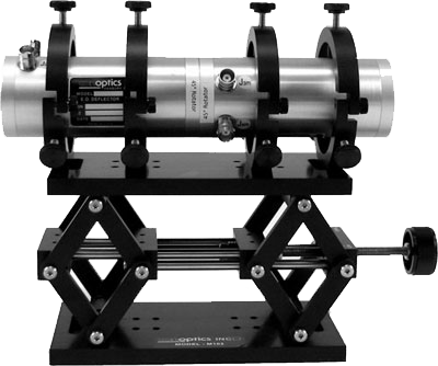
Conoptics provides standard electronics drivers for electro-optic deflection systems; however, we often customize the 310A to meet specific needs, achieving precision control for demanding use cases. Additionally, we commonly modify the systems with larger apertures, UV/IR operation, and higher voltage drivers. Furthermore, we create X-Y systems by coupling deflectors with a polarization rotator, and we also add sensors and feedback loops to enable beam-pointing stabilization. Customized quality control can be integrated with these sensors and feedback systems to optimize system performance for specific applications, ensuring tailored inspection processes and enhanced accuracy.
Key Applications
The versatility of beam deflection technology is evident in its wide range of applications across multiple industries. In material processing, precise control of laser beams allows for accurate cutting, welding, and surface modification, ensuring high-quality results. Laser printing relies on rapid and accurate beam deflection to produce high resolution images and intricate patterns on various substrates. In the realm of optical communications, beam deflection is essential for switching and routing optical signals, supporting high speed data transmission and network flexibility. Scientific research also benefits greatly from advanced beam deflection, with applications in microscopy and spectroscopy enabling detailed analysis of materials and biological samples. The unique properties of electro optic deflectors and acousto optic devices—such as high speed, high precision, and reliable control—make them indispensable tools in these and many other fields, driving innovation and expanding the possibilities of laser technology.
Optic Deflector Design
Designing an effective optic deflector involves a careful balance of materials, electrical input, and mechanical systems to achieve the desired performance. Electro optic deflectors typically use crystals like lithium niobate, which are paired with electrode structures to apply an electric field. This field alters the refractive index of the crystal, resulting in controlled beam deflection. In contrast, acousto optic devices utilize sound waves to modulate the refractive index, enabling dynamic beam steering. The choice of crystal, the configuration of the electrical input signal, and the integration with mechanical systems all play crucial roles in determining the accuracy, speed, and reliability of the deflector. Additional considerations include the wavelength of the laser beam, the size of the input aperture, and the required scanning speed and resolution for the specific application. By optimizing these design elements, engineers can create optic deflectors that deliver exceptional performance in material processing, laser printing, scientific research, and beyond, meeting the precise needs of each unique application.
List of Deflectors
Model 310A
| Aperture (mm) | 2.5mm |
| Deflection Efficiency | 1.5 micro-radians/volt |
| Capacitance, pf | 100 |
| Standard Spectral Range | 400nm-to-750nm |
| Length (mm) | 118mm |
| UV / DUV options | Yes |
Model 311A
| Aperture (mm) | 2.5mm |
| Deflection Efficiency | 3.0 micro-radians/volt |
| Capacitance, pf | 185 |
| Standard Spectral Range | 400nm-to-750nm |
| Length (mm) | 219mm |
| UV / DUV options | Yes |
| Collinear Configuration | Center In/Center Out |
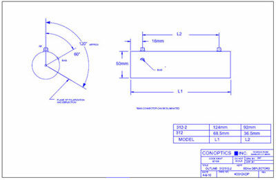
Model 312
| Aperture (mm) | 2.7mm |
| Deflection Efficiency | 0.6 micro-radians/volt |
| Capacitance, pf | 50 |
| Standard Spectral Range | 400nm-to-1100 |
| Length (mm) | 71mm |
| UV / DUV options | Yes |
| Collinear Configuration | Center In/Center Out |
Model 312-2
| Aperture (mm) | 2.7 |
| Deflection Efficiency | 1.2 micro-radians/volt |
| Capacitance, pf | 100 |
| Standard Spectral Range | 400nm-to-1100nm |
| Length (mm) | 125mm |
| UV / DUV options | Yes |
| Collinear Configuration | Center In/Center Out |
Model 400-80
| Aperture (mm) | 2.0mm |
| Deflection Efficiency | 4 micro-radians/volt |
| Capacitance, pf | 120pf |
| Standard Spectral Range | 700nm-to-1000nm or 1000nm-to-2000nm |
| Crystal Length (mm) | 80mm |
| UV / DUV options | No |
| Collinear Configuration | Center In/Center Out |
Model 400-120
| Aperture (mm) | 2.0mm |
| Deflection Efficiency | 7 micro-radians/volt |
| Capacitance, pf | 120pf |
| Standard Spectral Range | 700nm-to-1000nm or 1000nm-to-2000nm |
| Crystal Length (mm) | 120mm |
| UV / DUV options | No |
| Collinear Configuration | Center In/Center Out |
Amplifier Key Features:
Model 302RM Amplifier
| Cabinet | Driver and power supply in single cabinet |
| Test Feature | The built-in test feature enables users to check the Pockel Cell’s maximum transmission without adjusting the bias voltage. |
| Input Impedance | Choice of amplifier input impedance by rear panel switch (50ohm/1K ohm) |
| DC Bias | Improved DC biasing of the Pockel Cell enhances linearity, especially at higher bias voltages. |
| Voltage Range | The ±450VDC is controlled by a ten-turn potentiometer on the front panel, with a digital meter monitoring the differential bias to the E.O. Modulator. |
| Linearity | 10bits referenced to full scale (.1%) |
| Bandwidth | DC to >200Khz with 90pf load and 3M (RG-62) cables |
| Max. Output Drive Level | 750VP-P into 90pf load |
| Amplifier Input Signal | 2VP-P max into 50/1K ohms delivers 750VP-P out |
| Input Signal Format | Options include Unipolar positive, negative or bipolar |
| Input Power (AC) | 60W typical. Input power is both load (modulator) and frequency dependent. |
| Dimensions | 19″ Rack Mountable, 5.25″H(133mm) (3U) x 14″D (356mm) |
| Cooling | Forced air |
| Operating Environment | Designed for indoor laboratory use, the device operates at +5°C to +50°C with 20%-80% RH up to 32°C and at altitudes below 3000m. |
| Weight | 20lbs (9.07kg) |
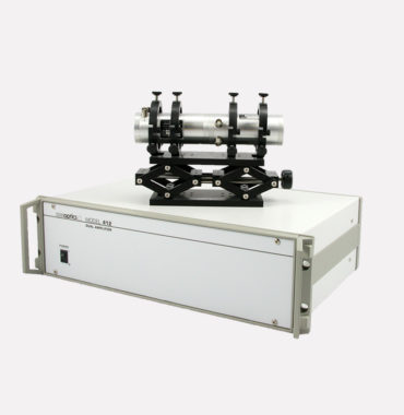
Model 412 Dual Amplifier
| Cabinet | Driver and power supply in single cabinet |
| Input Impedance | Choice of amplifier input impedance by rear panel switch (50ohm/1K ohm) |
| Gain | 375V/V Each Amplifier |
| Max. Output Drive Level | 750V P-P, each amplifier, driving 60pf load, 3m RG-62 cables |
| Detected Rise/Fall Time | Typically 2.5us driving 60pf with 3m RG-62 coax |
| Input Signal Format | Options include Unipolar POS/NEG or bipolar set by rear-panel slide switch |
| Input Power (AC) | Typically 70W (load and frequency dependent) |
| Dimensions | 19″ Rack Mountable, 5.25″H(133mm) (3U) x 14″D (356mm) |
| Cooling | Forced air |
| Operating Environment | Designed for indoor laboratory use, the device operates at +5°C to +50°C with 20%-80% RH up to 32°C and at altitudes below 3000m. |
| Weight | 20lbs (9.07kg) |
Model 25D Amplifier
| Cabinet | Driver and Power Supply in same cabinet |
| Input Impedance | 50ohms |
| Gain | +/- 400vDC |
| Max. Output Drive Level | 175V |
| Detected Rise/Fall Time | 8ns |
| Input Signal Format | TTL or Analog |
| Input Power (AC) | 300W |
| Dimensions | 45cm W x 44cm L x 17.5cm H |
| Cooling | Forced Air |
| Operating Environment | Designed for laboratory use (indoor only) |
| Weight | 32lbs |
Related Products
M312-1
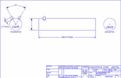
Model 310A Outline Drawing
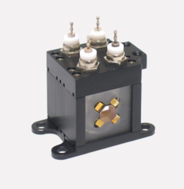
Model 320 Nutator Deflector

Model 412 Deflector Cutout
Technical Downloads
Related Products