Founded 1981
Over 3 Decades of ServiceCustomer Satisfaction
Consistently Ranked #1Made in USA
Proudly Made in the USAGlobal Representatives
19 Global Partners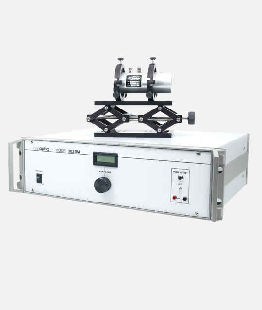
Call now to place your order.
Domestic: (800) 748-3349
International: (203) 743-3349
Configuration Options
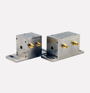
Conoptics manufactures a line of laser accessories, including driver electronics, beam deflectors, noise reduction tools, and optical isolators, all designed to meet diverse **modulation systems configuration options**. All electro-optic modulators listed in this data sheet are of the transverse field type, where the electric field produced by the applied signal voltage is perpendicular to the optical propagation direction. When selecting from the **modulation systems configuration options**, it is important to note that the voltage swing required by a modulator at a given operating wavelength to transition between the full-off state and the full-on state is called the Half Wave Voltage (V½).
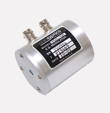
Electro-Optic Modulators
All electro-optic modulators in this data sheet are designed with various modulation systems configuration options to optimize performance for different applications. These modulators feature a transverse field type, where the electric field is perpendicular to the optical propagation direction. The required voltage swing, known as Half Wave Voltage (V½), can be adjusted by manipulating the crystal length to aperture ratio, a key factor in the modulation systems configuration options. V½ is proportional to wavelength, so longer wavelength devices often require higher ratios to work with existing driver output levels. Conoptics offers modulators using ADP, KD*P, and LTA crystals; each provides unique benefits, such as low piezoelectric resonance or reduced V½. Consequently, these features make them suitable for various high-performance laser applications.
Furthermore, its combination of high refractive index and relatively low dielectric constant allows designers to create modulators that fully utilize the intrinsic driver frequency response. Models in the 360 series exhibit piezoelectric resonances but they are discrete and very narrow. KD*P is used in the Model 350 series modulators. Moreover, in terms of optical transmission bandwidth and driver frequency response utilization, this series falls between the ADP and LTA versions. Consequently, Table 1 below provides the specifications for our ADP (240-to-800nm), KD*P (240-to-1100nm), and LTA (700-2000nm) series modulator product lines.
ADP Crystal Series Wavelength Limits (240 to 800 nm)*
| Model Number | V½ wave @ 500nm | V½ wave @ 830nm | Aperture Diameter | Resonances | Contrast Ratio @ 633nm | Length w/ Polarizer |
| M370 | 184 | 306 | 2.5mm | No | 500:1 | 158mm |
| M370 LA | 263 | 437 | 3.5mm | No | 500:1 | 158mm |
| M380 | 92 | 153 | 2.5mm | No | 500:1 | 253mm |
| M390 | 115 | 190 | 3.5mm | No | 500:1 | 272mm |
KD*P Crystal Series Wavelength Limits (240 to 1300nm)*
| Model Number | V½ wave @ 500nm | V½ wave @ 830nm | V½ wave @ 1064nm | Aperture Diameter | Resonances | Contrast Ratio @ 633nm & 1064nm | Length w/ Polarizer |
| M350-50 | 455 | 757 | 970 | 3.1mm | Yes | 500:1,700:1 | 106mm |
| M350-80 | 261 | 433 | 522 | 2.7mm | Yes | 500:1,700:1 | 137mm |
| M350-80LA | 360 | 600 | 720 | 3.5mm | Yes | 500:1,700:1 | 137mm |
| M350-105 | 226 | 376 | 472 | 3.1mm | Yes | 500:1,700:1 | 162mm |
| M350-160 | 130 | 216 | 275 | 2.7mm | yes | 300:1,500:1 | 215mm |
| M350-210 | 113 | 188 | 240 | 3.1mm | Yes | 300:1,500:1 | 268mm |
LTA Crystal Series Wavelength Limits (700 to 2000nm)
|
Model Number |
V½ wave @ 830nm | V½ wave @ 1064nm | V½ wave @ 2500nm | Aperture Diameter | Resonances | Contrast Ratio @ 1064nm | Length w/ Polarizer |
| M360-40 | 312 | 400 | 950 | 2.7mm | Yes | 200:1 | 95mm |
| M360-80 | 143 | 183 | 430 | 2.7mm | Yes | 100:1 | 137mm |
| M360-120 | 107 | 138 | 323 | 2.7mm | Yes | 100:1 | 174mm |
| M360-160 | 71 | 92 | 215 | 2.7mm | Yes | 100:1 | 215mm |
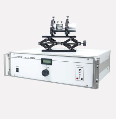
Table 2 Amplifier Details
| Model | Bandwidth | Rise/Fall Times | Max. Output V | Typical Drive Configuration | Output |
| 25A | DC-to-25MHz | 14ns | 145 | 100 Ohms B.L. | Linear |
| 25D | DC-to-30MHz | 8ns | 175 | 100 Ohms B.L. | Digital |
| 50 | DC-to-50MHz | 7ns | 90 | 50 Ohms B.L. | Linear |
| 100 | DC-to-100MHz | 3.5ns | 90 | 50 Ohms B.L. | Linear |
| 275 | DC-to-8MHz | 50ns | 275 | Lumped Capacitance | Linear |
| 302RM | DC-to-250KHz | 1 micro-sec | 750 | Lumped Capacitance | Linear |
| 302A | DC-to-1MHz | 350ns | 350 | Lumped Capacitance | Linear |
| 505 | 5MHz-to- 100MHz | 3.5ns | 44 | 50 Ohms S.E. | — |
| 550 | 20MHz-to-500MHz | 3.5ns | 140 | 50 Ohms S.E. | — |
Special Notes
- Contrast ratio measured with 1mm beam @ 1% point.
- Special Order wavelengths below 400nm are available, please contact sales@conoptics.com
- Special Clamped Version available to minimize piezo-electric resonances
- To find the ½ wave voltage, multiply the listed voltage by the wavelength ratio: (e.g., M350-50 @ 700nm = 455 x 1.4 = 637 Volts).
- The last digits of the 350 and 360 Series model numbers denote the crystal path length in millimeters.
Related Products